MODIS has 16 Emissive Bands (Bands 20-25 and bands 27-36), each with a 1 km ground resolution and wavelengths ranging from 3.75 to 14.24 micrometers (microns).
Key Uses of the MODIS Emissive Bands
| BAND | |
|---|---|
| Cloud Fraction | 24, 25, 33, 34, 35, 36 |
| Cloud Temperature | 32, 33, 34, 35, 36 |
| Cloud Temperature | 22, 23, 31 |
| Forest Fires & Volcanoes | 21, 31, 32 |
| Mid Troposphere Humidity | 27 |
| Sea Surface Temperature | 20 |
| Surface Temperature | 22, 23, 29, 31, 32 |
| Total Ozone | 30 |
| Troposphere Temperature | 24, 25 |
| Upper Troposphere Humidity | 28 |
L1B Emissive Calibration
The MODIS emissive calibration algorithm is designed to determine the at-aperture spectral radiance of the Earth scene with its associated uncertainties. Level 1A data is Earth-located raw sensor digital numbers and Level 1B data is Earth-located, calibrated data in physical units.

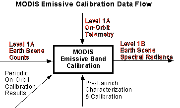
The RED print (upper half of figure) denotes parameters which change every scan. The BLACK print (lower half of figure) denotes periodic or pre-launch determined parameters.
The On-board Blackbody and Space View are used every scan to calibrate the emissive bands. The on-orbit emissive band MODIS calibration is a two point method which fits a nonlinear response by using pre-launch measurements.
Thermal Emissive Band (TEB) Calibration
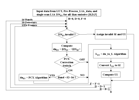
The following figure is a simplified flow diagram for the TEB calibration.

The major steps in this process are:
- Preprocess the L1A telemetry and onboard calibrator (OBC) data and retrieve the required LUT files
- Retrieve L1A Earth-view (EV) DN (digital number) and subtract the average (50 samples per scan) space-view (SV) background

- For Bands 32-36, apply optical crosstalk correction (Photons from Band 31 leak into Bands 32-36 via filter substrates)

- Use BB and SV DNs to calculate scan by scan linear calibration coefficients

where eS = source(s) emissivity
dnS = detector response to source (s) with background subtracted
LS = source (s) band averaged radiance over relative spectral response (RSR)
a0 and a2 = temperature dependent offset and nonlinear (quadratic) coefficient
RVS = response versus scan angle - Calculate the Earth-view radiance for each (BDF) (F=134 cross-track frames: there are no subframes for TEBs)

- Convert radiance to a scaled integer (SI). See below in Scaled Integer Conversion.
- Calculate RSS uncertainty and convert to an uncertainty index (UI). See below in Uncertainty Index
Uncertainty Index
For each pixel, the Uncertainty Index (UI), with a range of 0-15, is computed online using the following:
UI = scaling_factor[B]•ln(sEV/specified_uncertainty[B])
The band dependent scaling factors and specified uncertainty values come from LUT inputs. The RSS uncertainty, sEV (in percent), is computed dynamically.
UI utilizes the first four bits of an 8-bit unsigned integer, which yields a range of 0-15.
Scaled Integer Conversion
The TEB radiance values, LEV (W/m2/µm/sr), are scaled to an integer range of 0-32767 over the LUT-supplied dynamic range of Lmin to Lmax using:
SI(BDF)=32767*(LEV(BDF)- Lmin(BDF))/(Lmax(B)- Lmin(B))
LEV (a 32-bit floating-point number) is scaled to a valid integer of 0 to 32767, using 15 bits of a 16-bit integer number. SIs greater than 32767 are reserved for invalid data.
The LUT-fuished values of Lmin and Lmax are indexed by band only.
The RSB reflectance factors are scaled in a similar manner.

